Can custom hydraulic hoses Be Manufactured for Oil and Gas Applications?
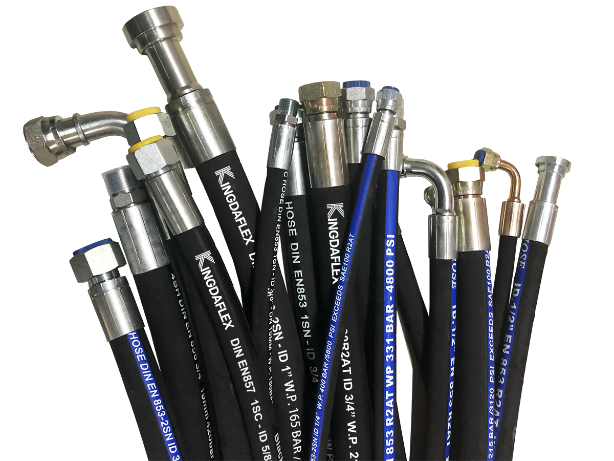
Yes. Custom hydraulic hoses can be manufactured for oil and gas equipment when pressure, fluid, temperature, routing, connection type, and external exposure are specified before production. Current ISO 18752:2025 covers reinforced hydraulic hoses in nominal sizes from 5 to 102 mm and includes oil-based fluid service from -40°C to +120°C for selected hose types. Commercial SAE 100R15 assemblies are available at 6,000 psi (42 MPa) working pressure, while SAE 100R12 products commonly operate around 4,000 psi. A suitable assembly may combine nitrile tubing, four or six spiral-steel reinforcement layers, abrasion-resistant covers, corrosion-resistant fittings, and application-specific crimp dimensions.
Oil and gas equipment does not give a hose one simple operating condition. A line on a drilling package may see 3,000-6,000 psi during normal service, repeated pressure pulses during actuator movement, oil on the cover, vibration from rotating equipment, and temperatures moving from sub-zero startup conditions to more than 100°C near operating machinery. Designing around only the normal pressure can leave the assembly unsuitable for the other conditions.
That pressure requirement starts with the whole assembly rather than the hose body. SAE J517 states that an assembly using SAE hose and compatible connectors must not exceed the lower working-pressure rating of its components. A 6,000 psi hose fitted with an end connection rated for 5,000 psi therefore remains a 5,000 psi assembly, regardless of the number printed on the hose cover. SAE J517 was revised in 2020, while many current product families also reference ISO 3862 and ISO 18752.
Pressure pulses require separate attention because pumps, valve switching, cylinders, and sudden equipment movement can generate short peaks above steady operating pressure. Reputable manufacturers qualify high-pressure constructions through repeated impulse cycling rather than a single static pressure check. One current SAE 100R12 four-spiral product, for example, has been tested to 1,000,000 impulse cycles while flexed at 50% of the standard SAE 100R12 bend radius.
Burst pressure should not be used as the allowable operating pressure. The working-pressure rating applies to normal service, while proof and burst values serve different test purposes.
Once pressure behavior is known, hose construction can be selected. Lower-pressure circuits may use textile or wire-braid reinforcement, while higher-pressure oilfield equipment often uses four or six layers of spiraled high-tensile steel wire. A commercial SAE 100R15 example uses four or six spiral layers and carries a 6,000 psi rating in 3/4-inch and 1-inch sizes, with minimum bend radii of about 10.5 and 13 inches respectively.
The reinforcement cannot be selected separately from the inner tube. Nitrile is widely used with petroleum-based hydraulic oils because it provides suitable oil resistance over common hydraulic temperature ranges. ISO 18752:2025 specifies oil-based hydraulic-fluid service from -40°C to +100°C for several hose types and up to +120°C for higher-temperature types, while some commercial hydraulic hoses are rated to +121°C or +125°C.
Water-containing fluids need different limits. ISO 18752:2025 lists water-based HFC, HFAE, HFAS, and HFB fluids at temperatures up to +70°C within its stated scope. A hose qualified for petroleum oil at 120°C should therefore not be assumed to provide the same temperature capability with a water-glycol or water-emulsion medium. Fluid name, concentration, operating temperature, and manufacturer compatibility data should be supplied with the request for quotation.
External material selection follows the fluid review because the cover faces a different environment from the tube. Offshore assemblies can be exposed to seawater, salt-laden air, UV radiation, hydraulic oil, drilling fluid, and repeated contact with steel structures. Abrasion-resistant synthetic-rubber covers are common, and specialized cover compounds can substantially extend wear resistance; one commercial product family reports up to 300 times the abrasion life of its standard cover under ISO 6945 hose-to-hose and hose-to-metal testing.
That level of cover protection still does not compensate for poor routing. A hose continually rubbing against a sharp bracket can lose material even when an upgraded cover is used, so clamps, guards, sleeves, and routing clearance need to be considered together. Industry practice also avoids twisting the hose during installation because the reinforcement is intended to manage internal pressure in a defined geometry, not torsional stress introduced by incorrect fitting orientation.
| Specification item | Typical engineering range or example | Why it is specified |
|---|---|---|
| Working pressure | 3,000-6,000 psi common in high-pressure hydraulic equipment | Sets hose, fitting, and coupling class |
| Temperature | About -40°C to +120/+125°C for selected oil-service hoses | Controls tube and cover compound |
| Reinforcement | 2 braid, 4 spiral, or 6 spiral layers depending on construction | Controls pressure and impulse capability |
| Hose ID | Roughly 1/4 in. to 2 in. for many equipment circuits | Influences flow velocity and pressure loss |
| Bend radius | Product-specific; about 265 mm for one 3/4-in. 6,000 psi hose | Controls routing space and flexing |
| Qualification | Up to 1,000,000 cycles on selected products | Provides data for repeated-pressure service |
Hose diameter comes next because oversizing and undersizing create different installation problems. A bore that is too small raises fluid velocity and pressure loss and can increase heat generation; a much larger hose costs more, takes more space, weighs more, and usually has a larger bend radius. Rather than copying the outside diameter of an old assembly, the manufacturer should work from inside diameter, flow requirement, connection size, and available routing space.
Routing dimensions should then be measured with the equipment in the positions it actually uses. A hose installed on a cylinder, top drive, winch, crane, or pipe-handling system may change position thousands of times. Length must allow movement without tension at the fitting and without creating excessive slack. An angled fitting can sometimes reduce a tight hose bend more effectively than adding extra hose length.
Connection geometry is another reason custom manufacturing is common. Oil and gas machinery may combine JIC 37-degree flare connections, SAE flanges, ORFS connections, NPT threads, BSP connections, or metric ends across equipment sourced from North America and Europe. Two ends can also require different connection families. Custom production allows each fitting, thread size, sealing method, and angular orientation to be defined before crimping.
Fitting material matters more when the assembly is used offshore. Carbon-steel fittings with protective plating are common, while stainless steel may be specified where corrosion exposure or project requirements justify it. Material compatibility should include mating components rather than the hose fitting alone, since mixed metals and long-term saltwater exposure can affect the connection. Marine applications can also bring SAE J1475, SAE J1942, or project-specific requirements into the specification process; SAE J517 has referenced marine standards in editions published before and after 2017.
Manufacturing accuracy becomes important after the components have been chosen. The hose must be cut cleanly, the correct coupling inserted to the required depth, and the ferrule crimped using validated tooling and diameter settings for that hose-and-fitting combination. Substituting a visually similar coupling is poor practice because fitting retention depends on the dimensions of the nipple, ferrule, reinforcement, and finished crimp.
Assembly inspection can therefore include overall length, coupling identity, insertion depth, crimp diameter, angular orientation, cleanliness, labeling, and visual condition. Pressure testing can be specified when the service, customer procedure, or equipment classification requires it. For a fleet with hundreds of hose assemblies, permanent tags containing an assembly number, size, manufacture date, and pressure class also make later replacement more reliable than identifying a worn hose from appearance alone.
A removed hose is useful as a dimensional reference, but it is not a complete engineering specification. Age, stretching, previous replacement work, unreadable markings, and incorrect historical substitutions can all affect what is found on the machine.
For that reason, reverse engineering should combine measurements from the old assembly with equipment data. The manufacturer should confirm working pressure, maximum fluid temperature, medium, port types, expected movement, minimum available bend radius, and environmental exposure before producing the replacement. A 2017 or 2020 equipment drawing can also reveal a connection or pressure class that is no longer readable on an aged hose.
Fire performance may add another requirement around drilling, mining-derived equipment designs, engine compartments, or areas where operators specify flame-resistant covers. Some high-pressure spiral hoses carry MSHA 2G flame-resistance acceptance in addition to SAE 100R12, EN 856 R12, or ISO performance references. Fire-resistant sleeving may also be placed over an assembly when the project specification requires additional external protection, but sleeve selection must account for hose movement and heat exposure.
Custom hydraulic assemblies should also be distinguished from a general industrial hose used for air, water, chemicals, material transfer, petroleum transfer, or suction service. Hydraulic power lines are designed around pressure containment, impulse performance, fitting retention, and controlled dimensional tolerances. Two hoses with the same 1-inch bore can therefore have very different reinforcement, bend radius, temperature capability, electrical behavior, and allowable working pressure.
Procurement data should reflect that engineering difference. A useful order specifies hose standard or performance class, nominal bore, working pressure, peak-pressure information when available, fluid type, fluid and ambient temperature, exact end connections, fitting orientation, overall length, bend requirements, external abrasion exposure, corrosion conditions, fire requirements, and requested documentation. ISO 18752:2025 now defines 10 pressure classes, four grades, and seven hose types, providing a structured reference where constant-pressure classification is preferred.
The finished assembly can then be matched to how the equipment is actually used instead of to a generic catalog description. A 6,000 psi offshore hydraulic line exposed to salt spray and repeated articulation may require spiral reinforcement, an oil-resistant nitrile tube, a high-abrasion cover, corrosion-resistant fittings, controlled bend geometry, identification marking, and documented pressure capability; a stationary 3,000 psi return or auxiliary circuit may need a lighter construction. Manufacturing both as identical hoses would add cost in one location and may provide inadequate performance in the other.